Analyzing Die-cast Mold Temperatures and Shrinkage Holes
Abstract: Aluminum alloy hydraulic valve bodies used in automobile automatic transmissions are prone to air entrapment and shrinkage cavities due to their complex structure, tortuous oil circuits, significant differences in wall thickness, and poor die-cast processability, posing great challenges to mold design and die-cast production process control.
The defect rate of a company's aluminum alloy hydraulic valve body remains high, with 50% of the products being unqualified. The main reason for scrapping is the exposure of internal shrinkage holes in the product after machining. This article explains the mechanism of shrinkage hole formation from multiple dimensions and uses cooling water to control mold temperature and transfer defects, thereby improving product qualification rate.
1. Product features
Size: 240*180㎜
Material: ADC12
Process: die casting
Defect location: bottom of bearing holes, as shown in Figure 1
Product defect rate: 47.5%
Reason for defects: shrinkage holes
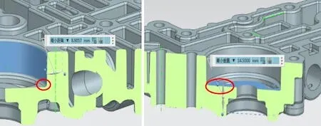
Figure 1 Defect areas of bearing holes
1. Analysis of defect formation mechanism
Through three-dimensional and defective product physical sectioning, it is found that the wall thickness at the defect position of the bearing hole is significantly thicker than other parts. Combined with mold flow software to analyze liquid tracking, temperature, folded oxide, and gas content, the results show that two metal flows intersect and fill in the bearing hole, and the regional heat capacity is large, making it the last solidified part. During solidification, the molten metal gradually changes from liquid to solid, resulting in volume shrinkage, and the residual gas in this area is sucked into the shrinkage cavity. Other thin-walled areas solidify first, causing the filling and shrinkage channels to be blocked, thus forming shrinkage holes, as shown in Figure 2.
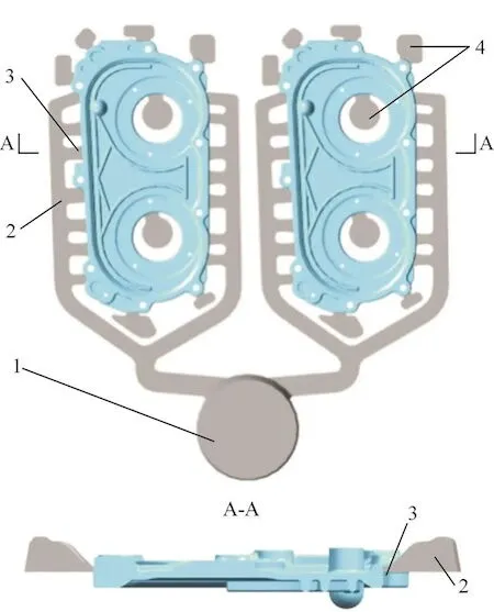
Figure 2 Mold flow software analysis view
A. Material liquid tracking B. Temperatures C. Folding oxide D. Gas content
2. Improvement plan and verification
After analyzing the above defect formation mechanism, the current product structure can no longer be optimized. Based on the strategy of implementing solutions from easy to difficult, we first try to improve the process by gradually adjusting the mold temperature of the thick part of the bearing hole, changing the solidification sequence of the defective area, realizing defect transfer, and preventing defects from being exposed during machining (defects exist inside the product but do not affect performance). Therefore, four temperature adjustments were made for the thick area of the bearing hole, and the following experiments were carried out while keeping other process conditions unchanged:
1. Turn off the spot cooling of the bearing hole and reduce the spraying amount to keep the temperature between 220℃ and 240℃.
2. Turn off the spot cooling of the bearing hole and increase the spraying amount to keep the temperature between 190℃ and 210℃.
3. Enable the spot cooling of the bearing hole and increase the time of spot cooling water flow to keep the temperature between 150℃ and 170℃.
4. Change the cooling water of the bearing hole to long flow, keeping the temperature between 90℃ and 110℃, as shown in Figure 3.
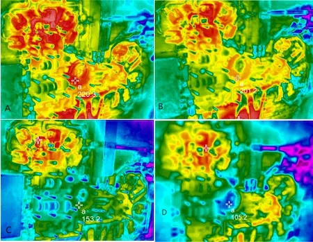
Figure 3 Adjusting the temperature of the bearing hole area
The defect rate of a company's aluminum alloy hydraulic valve body remains high, with 50% of the products being unqualified. The main reason for scrapping is the exposure of internal shrinkage holes in the product after machining. This article explains the mechanism of shrinkage hole formation from multiple dimensions and uses cooling water to control mold temperature and transfer defects, thereby improving product qualification rate.
1. Product features
Size: 240*180㎜
Material: ADC12
Process: die casting
Defect location: bottom of bearing holes, as shown in Figure 1
Product defect rate: 47.5%
Reason for defects: shrinkage holes

Figure 1 Defect areas of bearing holes
1. Analysis of defect formation mechanism
Through three-dimensional and defective product physical sectioning, it is found that the wall thickness at the defect position of the bearing hole is significantly thicker than other parts. Combined with mold flow software to analyze liquid tracking, temperature, folded oxide, and gas content, the results show that two metal flows intersect and fill in the bearing hole, and the regional heat capacity is large, making it the last solidified part. During solidification, the molten metal gradually changes from liquid to solid, resulting in volume shrinkage, and the residual gas in this area is sucked into the shrinkage cavity. Other thin-walled areas solidify first, causing the filling and shrinkage channels to be blocked, thus forming shrinkage holes, as shown in Figure 2.

Figure 2 Mold flow software analysis view
A. Material liquid tracking B. Temperatures C. Folding oxide D. Gas content
2. Improvement plan and verification
After analyzing the above defect formation mechanism, the current product structure can no longer be optimized. Based on the strategy of implementing solutions from easy to difficult, we first try to improve the process by gradually adjusting the mold temperature of the thick part of the bearing hole, changing the solidification sequence of the defective area, realizing defect transfer, and preventing defects from being exposed during machining (defects exist inside the product but do not affect performance). Therefore, four temperature adjustments were made for the thick area of the bearing hole, and the following experiments were carried out while keeping other process conditions unchanged:
1. Turn off the spot cooling of the bearing hole and reduce the spraying amount to keep the temperature between 220℃ and 240℃.
2. Turn off the spot cooling of the bearing hole and increase the spraying amount to keep the temperature between 190℃ and 210℃.
3. Enable the spot cooling of the bearing hole and increase the time of spot cooling water flow to keep the temperature between 150℃ and 170℃.
4. Change the cooling water of the bearing hole to long flow, keeping the temperature between 90℃ and 110℃, as shown in Figure 3.

Figure 3 Adjusting the temperature of the bearing hole area
A. Calibrated at 220.3℃ B. Calibrated 201.2℃ C. Calibrated at 153.2℃ D. Calibrated at 105.2℃
After each temperature adjustment, a thermal imager was used to measure the temperature. Once the required temperature was reached, 100 pieces were produced. Simultaneous flaw detection was performed to confirm the change in defects in the bearing hole area. Separate processing verification was performed, and random samples were selected from qualified products for sectioning to confirm the depth of the defect from the processing surface (see Table 1, Figure 4, and Figure 5).
Table 1 Mold temperature adjustment verification results
| Verification batch | Fuel temperature at the machine side | Bearing hole temperature | Verification quantity | Qualified rates |
| 1 | 670°C | 220°C to 240°C | 100 | 27.62% |
| 2 | 670°C | 190°C to 210°C | 100 | 37.63% |
| 3 | 670°C | 150°C to 170°C | 100 | 71.54% |
| 4 | 670°C | 90°C to 110°C | 100 | 100% |
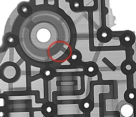
Figure 4 The hole at the bottom of the bearing hole transferred to the side wall
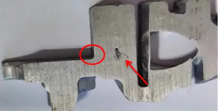
Figure 5 Actual image of the side section of the bearing hole
3. Conclusion
Through the above four temperature adjustment verifications, the production process of the product was confirmed. In subsequent production under the curing process conditions, no shrinkage hole processing exposure was found at the bottom of the bearing hole, and the overall product qualification rate was stable, exceeding 95%. Based on the above verification, adjusting the partial temperature of the mold can effectively transfer shrinkage holes and reduce defects so that they are not exposed during machining, thereby improving the product qualification rate and reducing production costs.
Related News
- Industrialization of the Composite 3D Printing for General Motors
- Porsche and GM Have Obtained Achievement in 3D Printing Auto Parts Technology
- Development of Aluminum Alloy Die Castings for Automobile Steering Knuckles (Part Two)
- Development of Aluminum Alloy Die Castings for Automobile Steering Knuckles (Part One)
- Die Casting Technologies of Automobile Structural Parts (Part Three)
- The Die Casting Technology of Automobile Structural Parts (Part Two)
- The Die Casting Technology of Automobile Structural Parts (Part One)
- Application of Heat-Free Aluminum Alloys to Integrated Die-Casting
- Mechanical Properties and Microstructure of Heat-Free Alloys
- Designing Die-Cast Molds for Complex Shells


