Designing Die-Cast Molds for Complex Shells
On this page
Abstract
The characteristics of die-casting shell parts were analyzed, and the casting simulation software ProCAST was used to assess the flow filling, heat balance, and temperature field of die-casting molds, providing verification for the design's rationality of the mold's casting and cooling systems. Actual die-casting production demonstrates that the mold design is sound and that the quality of the die-cast parts is high.
As industries such as automotive, aerospace, and electrical appliances develop, the use of aluminum alloy die-casting parts is increasingly widespread to improve quality and meet design requirements like energy saving and pollution reduction. Currently, die-casting is one of the most widely used processes in aluminum alloy forming for automobiles. As a method for forming final and near-final shapes, die casting produces thin-walled, complex structures with clear contours, dense materials, high-strength castings, and high production efficiency, making it ideal for mass production. Die casting molds are the primary equipment in die casting production, directly affecting the quality, cost, and efficiency of die castings. This paper presents a ProCAST-based simulation analysis of complex casing parts, supporting the design of die casting molds.
As industries such as automotive, aerospace, and electrical appliances develop, the use of aluminum alloy die-casting parts is increasingly widespread to improve quality and meet design requirements like energy saving and pollution reduction. Currently, die-casting is one of the most widely used processes in aluminum alloy forming for automobiles. As a method for forming final and near-final shapes, die casting produces thin-walled, complex structures with clear contours, dense materials, high-strength castings, and high production efficiency, making it ideal for mass production. Die casting molds are the primary equipment in die casting production, directly affecting the quality, cost, and efficiency of die castings. This paper presents a ProCAST-based simulation analysis of complex casing parts, supporting the design of die casting molds.
1. Shell Parts
The die-casting part is made from A380, used as the valve body for the oil pipeline, as shown in Figure 1. The part's structure is relatively complex, with numerous rib structures. After die-casting, the inner side of the thin wall at the three end openings of the valve body must be threaded to connect the oil pipe parts. To ensure the strength of the threaded connection and meet the airtightness requirements of the valve body, these open thin walls must be of high quality, dense, and free of gas holes. The shell's weight is 2.952 kg, and its overall thickness is relatively thin, with the main wall thickness around 5 mm. However, the wall thickness varies significantly, ranging from 2.5 mm to 9.4 mm.

Figure 1 Shell parts

Figure 1 Shell parts
2. Die-Casting Mold Design
2.1 Parting Surface and Pouring System
Based on the structural characteristics of the casing die-casting, the parting surface is selected at the largest opening of the casing. The pouring system plays an important role in controlling the flow direction and state of the molten metal in the mold cavity, exhaust conditions, and pressure transmission of the mold, and it can also adjust the filling speed, filling time, and temperature distribution of the mold. The casing is a cylindrical casting with six inner gates positioned at the end of the largest cylinder, allowing the molten metal to enter the cavity along the wall, avoiding direct impact on the core and first filling the bottom of the cavity, which aids in gas exhaust. Figure 2 shows the pouring system.
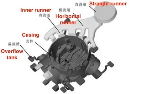
Figure 2 Shell casting pouring systems

Figure 2 Shell casting pouring systems
2.2 Cooling System
The layout of the cooling system is crucial for the forming and deformation of the product. To achieve effective cooling, a combination of spot cooling and cooling water channels is used. Figure 3 illustrates the distribution of cooling water channels inside the die-casting mold. Each insert has an independent cooling water channel or spot cooling system. These water channels are positioned at the center of each thin-wall opening of the casting to enhance the cooling of each thin-walled section.
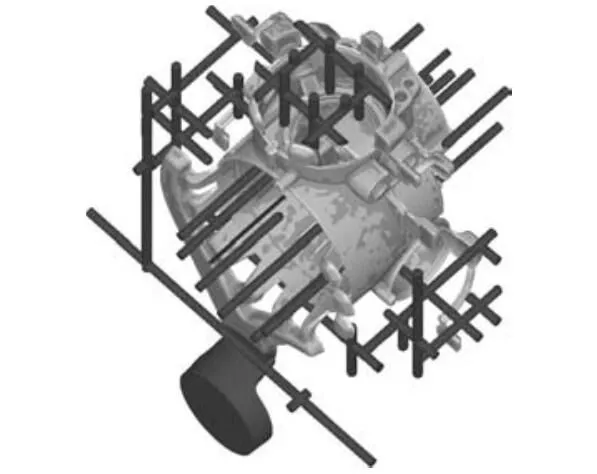
Figure 3 Cooling water channel and spot cooling layout

Figure 3 Cooling water channel and spot cooling layout
2.3 Mold Structure
This secondary mold is relatively large, with the mold frame measuring 990 mm in length and 910 mm in width. Figure 4 shows the mold core structure. The fixed mold is a single unit, while the movable mold contains insert 5. The openings around the shell are formed by four sliders, and core pulling is achieved by four hydraulic cylinders. Replaceable long pin cores are used in the four deep hole sections. Figure 5 shows the mold diagram.
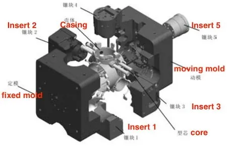
Figure 4 Moving and fixed molds and inserts
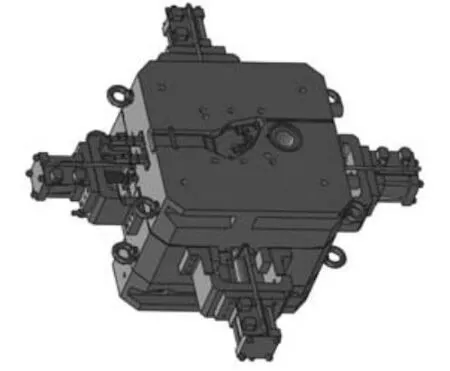
Figure 5 The Mold diagram

Figure 4 Moving and fixed molds and inserts

Figure 5 The Mold diagram
3. CAE Analysis
HyperMESH is used to create the surface mesh for the casting and the mold, and the high-quality surface mesh model is then imported into MeshCAST in ProCAST. After verification, a tetrahedral mesh is generated. The mesh count for the die casting and mold totals 4.45 million. Boundary conditions are set in PreCAST, followed by simulation calculations.
3.1 Boundary Conditions
The casting is made from A380, while the mold is made from H13 steel. The aluminum liquid pouring temperature is set at 650℃, the mold preheating temperature at 220℃, the gate speed at 3 m/s, and the water cooling temperature at 20℃. According to relevant literature, the heat transfer coefficient is set to 20,000W/(㎡·K) between the mold and the casting, 1,000 W/(㎡·K) between the movable and fixed molds, 100 W/(㎡·K) between the mold and air, and 100 W/(㎡·K) between the release agent and the mold. The cooling water channel diameter is 10 mm, the cooling water flow rate is 1 m/s, and the heat transfer coefficient between the cooling water and the mold is calculated to be 5,000 W/(㎡·K). The die casting production cycle can be divided into four stages:
① metal liquid filling, pressure holding, and solidification
② mold opening and casting removal
③ mold release agent spraying
④ mold closing
The four stage durations are 40 s, 15 s, 5 s, and 10 s, respectively, with a total cycle time of 70 s. The gate pouring speed is set to 3 m/s, and the temperatures of both the release agent and air are set to 20℃.
3.2 Filling Analysis
Figure 6 illustrates the flow field distribution of the molten metal at various times during the filling process. The entire filling process takes 0.08 second. Initially, the molten metal enters the cavity along the wall and flows smoothly. The flow rates of the six streams of molten metal are similar. The molten metal on both the left and right sides of the casting is filled sufficiently and evenly. The overall filling process is efficient, avoiding the 'eddy currents' formed by the molten metal flowing back along the wall cavity. The final position of the molten metal is the overflow groove farthest from the gate, which effectively completes the filling process.
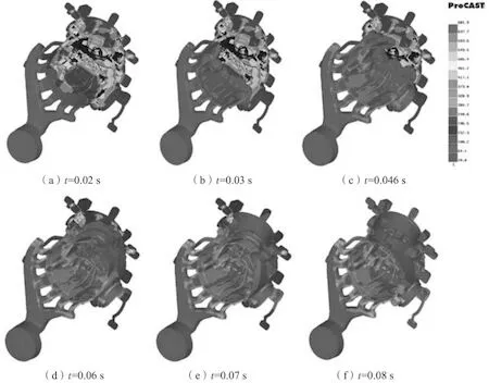
Figure 6 Flow field of the shell casting filling process

Figure 6 Flow field of the shell casting filling process
3.3 Temperature Field Analysis of the Die Casting Process
During the die casting cycle, the primary heat source for the mold is the high-temperature molten metal, while heat is dissipated into the air and partially removed by the flowing cooling water. When the heat absorbed by the mold equals the heat dissipated within a unit of time, achieving an equilibrium state, it is referred to as the thermal balance of the mold. Points 1, 2, and 3 in Figure 7 indicate locations on the cavity surfaces of the movable mold, fixed mold, and casting, respectively. The temperature-time curve is plotted in Figure 8. As shown, the mold reaches thermal equilibrium after 10 die-casting cycles.
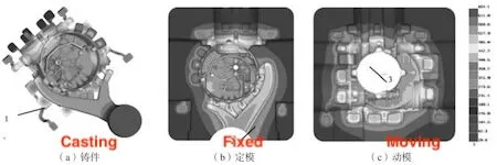
Figure 7 Selected points on the mold and casting
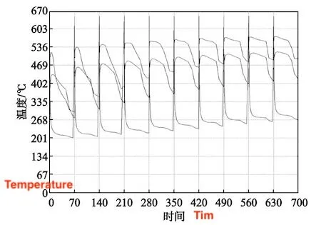
Figure 8 Temperature-time curve of three points

Figure 7 Selected points on the mold and casting

Figure 8 Temperature-time curve of three points
3.4 Temperature Field Analysis
The temperature field of the mold during the 11th cycle, after reaching thermal equilibrium, is selected for analysis. Figure 9 illustrates the temperature field changes in the movable mold, fixed mold, and insert 5 throughout one cycle. Three representative moments are selected for analysis: the 0th, 4.98th, and 55th seconds within a cycle, corresponding to before filling, during pressure maintenance, and while spraying the release agent. Before filling, the temperature field of the mold is relatively uniform, with an average temperature of approximately 370℃. As the molten metal fills the cavity, the surface temperature of the mold rises sharply. During the pressure holding stage, the mold gradually cools as heat is dissipated into the air and partially carried away by the cooling water. When the mold is opened and the parts are removed, the surface temperature of the cavity rapidly decreases as the mold release agent is sprayed, aided by air quenching, causing most of the cavity's surface temperature to drop below 420℃. As depicted in Figure 9, the temperature distribution across the movable mold and each insert is relatively uniform, with minimal changes in the cavity surface's temperature gradient, indicating that the cooling system is well-designed.
Figure 9 Temperature field of the movable mold, fixed mold and insert 5 at different times in one cycle
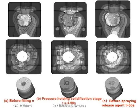
Figure 9 Temperature field of the movable mold, fixed mold and insert 5 at different times in one cycle

4. Die Casting Production
The mold has been used in the production of castings for this project. The die casting after machining is shown in Figure 10. There are no gas holes in the three thin walls that require threading, and the quality of the thin walls is excellent; the threaded part is complete and free of gas holes, meeting both the strength requirements for the threaded connection and the air tightness requirements of the valve body.

Figure 10 Shell parts after processing

Figure 10 Shell parts after processing
5. Conclusion
Based on CAE analysis, the die-casting mold design for aluminum alloy shell parts was completed. The CAE analysis results confirmed the validity of the mold casting system and cooling system. The actual production of the mold demonstrated that the three thin walls requiring processing were dense and free of gas holes. This met the requirements for thread connection strength and valve body air tightness, confirming the reasonableness of the mold design.
Related News
- Industrialization of the Composite 3D Printing for General Motors
- Porsche and GM Have Obtained Achievement in 3D Printing Auto Parts Technology
- Development of Aluminum Alloy Die Castings for Automobile Steering Knuckles (Part Two)
- Development of Aluminum Alloy Die Castings for Automobile Steering Knuckles (Part One)
- Die Casting Technologies of Automobile Structural Parts (Part Three)
- The Die Casting Technology of Automobile Structural Parts (Part Two)
- The Die Casting Technology of Automobile Structural Parts (Part One)
- Application of Heat-Free Aluminum Alloys to Integrated Die-Casting
- Mechanical Properties and Microstructure of Heat-Free Alloys
- Designing Die-Cast Molds for Complex Shells


