Die-cast Aluminum Castings for High-speed Rail Rocker Arm Shells
High-speed maglev trains are the focus of China's transportation development, and Aluminum Die-Casting for rocker arm shells are key load-bearing components. To achieve the localization of key components for 600 km-class and above wheelless rail high-speed trains, the development of rocker arm shell castings is particularly important.
1. Structural Characteristics and Technical Requirements of Castings
The overall dimensions of the rocker arm shell casting are approximately 1,200 mm × 160 mm × 80 mm (see Figure 1). The casting is an integral flat plate structure with a small wall thickness (average wall thickness of about 4 mm) and multiple thermal nodes. It is a Class I casting, and the mechanical properties of the body cutting are required to be: tensile strength ≥ 280 MPa, yield strength ≥ 235 MPa, and elongation ≥ 3%. The casting needs to withstand at least 10 million fatigue cycle loads, and the fatigue performance of the casting body cutting is required to meet the following requirements: when R = -1 and the maximum fatigue stress is 90 MPa, the fatigue life is not less than 107 cycles.
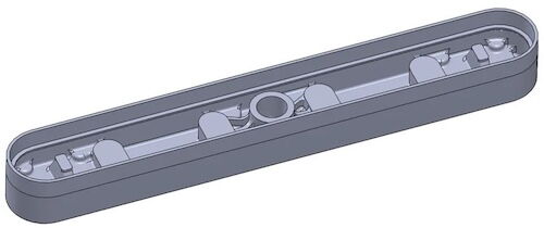
Figure 1: Three-dimensional model of rail rocker housing casting
Figure 1: Three-dimensional model of rail rocker housing casting
2. Experimental Materials and Methods
The casting is made of ZL105A alloy, and its chemical composition complies with GB/T 1173-2013 standards. The alloy is smelted in a resistance furnace, and the following steps are performed:
Melting: Maintain at 850℃ until melting is complete, stir for 30 minutes, cool to 700℃, add pure Mg, and stir for 15 minutes.
Refining: Use 0.6% and 0.78% refining agents (C2Cl6) and Ar refining spray for 20 minutes for degassing and slag removal, then add Al-5Ti-1B wire for refinement.
Casting: Sand mold low-pressure casting is used, and the obtained casting is subjected to T6 heat treatment (525℃ for 6 hours for solid solution, water quenching, 160℃ for 5 hours for aging).
Mechanical Properties Test:
The tensile rate is 1 mm/min, the fatigue test stress ratio is R = -1, the maximum stress is 90 MPa, and the loading frequency is 120 Hz.
Microstructure Observation: LEICA DM1750M metallographic microscope and Sigma 300 scanning electron microscope.
Melt Hydrogen Content: RT-CQ1000 aluminum melt hydrogen meter.
3. Experimental Results and Discussion
3.1 ZL105A Alloy Melt Treatment
To ensure that the Die-Cast Aluminum Parts has good fatigue performance, the microstructure needs to be dense and free of shrinkage and crack defects. The Si content in ZL105A alloy is 4.5%-5.5%, and the Mg content is 0.40%-0.55%. It easily absorbs H, resulting in pinhole defects. Therefore, enhanced refining is used to reduce the degree of pinholes.
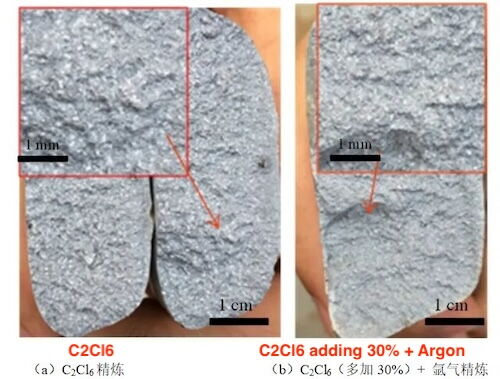
Figure 2: Fracture morphology analysis under different refining processes
Figure 2 shows the fracture of the test block before and after refining: The fracture of the melt after refining is gray, with obvious pinholes and a small amount of black inclusions on the cross-section. The fracture, after increasing the amount of refining agent and using high-purity argon gas injection treatment, has a reduced number and smaller size of white spots (pinholes). The Cl2 bubbles generated by the decomposition of C2Cl6 at high temperatures discharge slag and H, but the bubbles are large, and the H absorption effect is average. High-purity argon gas injection absorbs H better through small bubbles, but the slag removal effect is poor. Therefore, combining C2Cl6 refining with high-purity argon gas refining achieves a better melt purification effect.
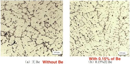
Figure 3: ZL105A Alloy Metallographic Structure
Figure 3 shows the metallographic structure of a single-cast test bar with and without Be added to the alloy (Be addition is 0.15%), and Table 2 compares the hydrogen content of the melt: The hydrogen content of the aluminum melt with Be added is significantly lower than that without Be, and the eutectic Si phase is finer. Be and Fe form Be-Fe precipitation phases, which serve as the nucleation core for eutectic Si and refine the eutectic Si. Be combines with O to form BeO, which slows down the oxidation rate of the alloy liquid, reduces the absorption of H by the melt, and maintains purity.
Table 2: Hydrogen Content in Aluminum Liquid of ZL105A Alloy with and without Be Added μg/g
Figure 2: Fracture morphology analysis under different refining processes
Figure 2 shows the fracture of the test block before and after refining: The fracture of the melt after refining is gray, with obvious pinholes and a small amount of black inclusions on the cross-section. The fracture, after increasing the amount of refining agent and using high-purity argon gas injection treatment, has a reduced number and smaller size of white spots (pinholes). The Cl2 bubbles generated by the decomposition of C2Cl6 at high temperatures discharge slag and H, but the bubbles are large, and the H absorption effect is average. High-purity argon gas injection absorbs H better through small bubbles, but the slag removal effect is poor. Therefore, combining C2Cl6 refining with high-purity argon gas refining achieves a better melt purification effect.
Figure 3: ZL105A Alloy Metallographic Structure
Figure 3 shows the metallographic structure of a single-cast test bar with and without Be added to the alloy (Be addition is 0.15%), and Table 2 compares the hydrogen content of the melt: The hydrogen content of the aluminum melt with Be added is significantly lower than that without Be, and the eutectic Si phase is finer. Be and Fe form Be-Fe precipitation phases, which serve as the nucleation core for eutectic Si and refine the eutectic Si. Be combines with O to form BeO, which slows down the oxidation rate of the alloy liquid, reduces the absorption of H by the melt, and maintains purity.
Table 2: Hydrogen Content in Aluminum Liquid of ZL105A Alloy with and without Be Added μg/g
| Adding Be | No | Yes |
| Hydrogen content | 0.20 | 0.12 |
3.2 Casting Process Design and Numerical Simulation
There is a hot spot area in the rocker housing casting, so an inner runner is set below the hot spot to avoid internal shrinkage defects caused by insufficient shrinkage compensation. Since the height of the casting is only 160 mm, the width is 80 mm, and the average wall thickness of the vertical surface is only 4 mm, considering the modeling, ease of operation for unpacking, and effectiveness of shrinkage compensation, the bottom pouring + gap pouring system is adopted, and the low-pressure casting method is used to form it (see Figure 4). With this pouring system, the rationality of the casting process is calculated.
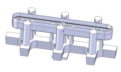
Figure 4: Schematic Diagram of the Design of the Pouring System of the Rocker Housing
The casting process of the rocker housing casting is simulated and calculated using ProCAST simulation software. The pouring process parameters used for the simulation are shown in Table 3.
Table 3: Casting Process Parameters
| Liquid rising speeds/(mm.s-1) | Filling speeds/tmm.s-1) | Liquid lifting pressure/KPa | Filling pressure/KPa | Shell time/s |
Pressure holding pressure/KPa | Pouring temperature/℃ |
| 50 | 50 | 25 | 50 | 1200 | 75 | 710 |
3.2 Casting Process Design and Numerical Simulation
Figures 5 and 6 show the temperature field and solid phase ratio during the solidification process of the rocker housing, respectively. It can be seen that the temperature gradient distribution of the rocker housing casting is reasonable during the solidification process after the metal liquid is filled, and the last solidified area is concentrated in the bottom pouring system, ensuring that the casting solidifies in sequence and achieves better structure and higher mechanical properties.
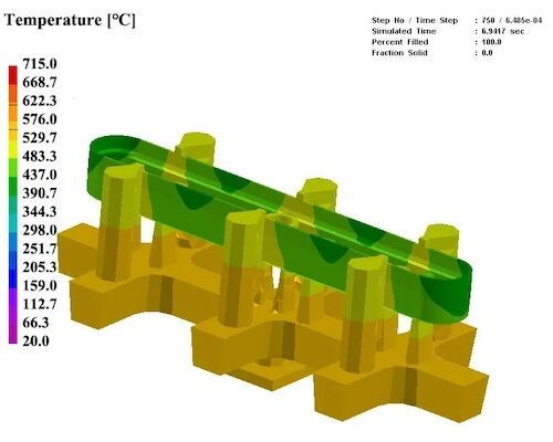
Figure 5: Temperature Field during the Solidification Process of the Rocker Housing
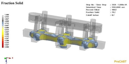
Figure 6: Solid Phase Ratio during the Solidification Process of the Rocker Housing
Figure 7 shows the possible locations of shrinkage according to the Niyama criterion. The simulation results show that under these process conditions, the hot spots are effectively compensated, and the casting has no shrinkage overall. Figure 8 shows the pressure distribution and transmission of aluminum liquid during the simulated filling process. It can be seen that during low-pressure filling, the aluminum liquid pressure gradually decreases from bottom to top, establishing a good sequential solidification pressure gradient, which can achieve effective compensation of the casting.
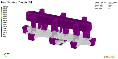
Figure 7: Shrinkage Ratio during the Solidification Process of the Rocker Housing
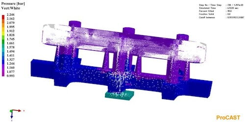
Figure 8: Pressure Distribution during the Pouring Process of the Rocker Housing
Combining the above simulation results, it can be seen that the pouring process design of the rocker housing casting is reasonable. In addition, to further ensure the internal quality of castings in the actual production process, a conformal chiller is set in the thick and large parts (the thickness of the chiller is 10 mm, see the red area in Figure 9) to accelerate the quenching; at the same time, a filter is set at the intersection of the cross runner and the inner runner to reduce the risk of inclusions in the casting body.
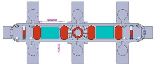
Figure 9: Schematic Diagram of the Chiller Arrangement and the Body Cutting Position
Figure 5: Temperature Field during the Solidification Process of the Rocker Housing
Figure 6: Solid Phase Ratio during the Solidification Process of the Rocker Housing
Figure 7 shows the possible locations of shrinkage according to the Niyama criterion. The simulation results show that under these process conditions, the hot spots are effectively compensated, and the casting has no shrinkage overall. Figure 8 shows the pressure distribution and transmission of aluminum liquid during the simulated filling process. It can be seen that during low-pressure filling, the aluminum liquid pressure gradually decreases from bottom to top, establishing a good sequential solidification pressure gradient, which can achieve effective compensation of the casting.
Figure 7: Shrinkage Ratio during the Solidification Process of the Rocker Housing
Figure 8: Pressure Distribution during the Pouring Process of the Rocker Housing
Combining the above simulation results, it can be seen that the pouring process design of the rocker housing casting is reasonable. In addition, to further ensure the internal quality of castings in the actual production process, a conformal chiller is set in the thick and large parts (the thickness of the chiller is 10 mm, see the red area in Figure 9) to accelerate the quenching; at the same time, a filter is set at the intersection of the cross runner and the inner runner to reduce the risk of inclusions in the casting body.
Figure 9: Schematic Diagram of the Chiller Arrangement and the Body Cutting Position
4. Production Verification
The rocker housing casting was produced according to the above process, and the actual casting is shown in Figure 10. After X-ray inspection, no shrinkage defects were found inside the casting, which is consistent with the results of the ProCAST simulation; no pinholes or inclusions were found, and the internal quality met the requirements of GB 9438-2008 Class I castings, achieving successful trial production. The rocker housing was inspected for dimensions using a three-coordinate measurement platform, and all dimensions were found to be within specification. The casting was dissected, and the mechanical and fatigue properties of the rocker housing casting body samples are shown in Table 4, all of which meet the technical specifications. The tensile fracture of a sample cut from the body is shown in Figure 11. It can be seen that there are numerous tear edges across the entire section, and the fracture features a large number of dimples and small cleavage planes. The dimples are numerous and deep, indicating a mixed fracture mode of ductile and cleavage fractures. No obvious shrinkage, pores, or other defects were found on the fracture, and the overall plasticity is good.
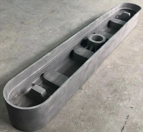
Figure 10: Qualified Rocker Arm Housing Castings
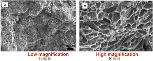
Figure 11: Tensile Fracture Structure of the Casting Body
Table 4: Mechanical Properties and Fatigue Service Life of Casting Body Sampling
Figure 10: Qualified Rocker Arm Housing Castings
Figure 11: Tensile Fracture Structure of the Casting Body
Table 4: Mechanical Properties and Fatigue Service Life of Casting Body Sampling
| Items | σb/MPa | σ0.2/MPa | б3/% | items | Cycle-index Nf/times |
| 1 | 310 | 255 | 4.7 | 1 | 1010398 |
| 2 | 312 | 253 | 4.9 | 2 | 1 001 406 |
| 3 | 318 | 261 | 5.6 | 3 | 1 005 047 |
| 4 | 314 | 256 | 4.2 | ||
| 5 | 320 | 249 | 4.6 | ||
Figure 12 shows the fracture morphology of the rocker arm housing fatigue specimen. It can be seen that the crack source is near the surface (no oxides, shrinkage, pinholes, or other defects are observed at the crack source, and the crack source may have started from the stress concentration area of the test rod processing), and the crack initiation and extension area account for a large proportion of the entire fracture (nearly 40%), demonstrating good fatigue performance. Some bright planes were observed in the crack extension area, which may have been caused by the wear of the upper and lower planes during the crack extension process. In the instantaneous fracture zone, a large number of tearing edges and small dimples are visible. The fracture is primarily a plastic fracture with mixed cleavage, showing good plasticity, which is consistent with the characteristics of the tensile fracture surface.
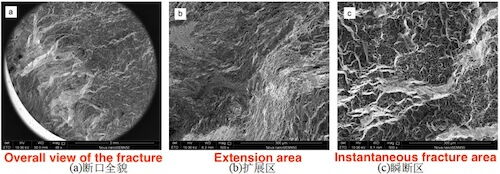
Figure 12: Fatigue Fracture Structure of the Casting Body
5. Conclusion
(1) Through composite refining and Be addition, the performance of the ZL105A rocker arm housing casting body samples is as follows: tensile strength is 318 MPa, yield strength is 261 MPa, elongation is 5.6%, and fatigue life exceeds 107 cycles, demonstrating good overall performance.
(2) Based on the ProCAST simulation results, the sand mold low-pressure casting method, combined with the bottom injection and gap casting process, was used to produce a rocker arm housing casting with satisfactory internal quality.
(2) Based on the ProCAST simulation results, the sand mold low-pressure casting method, combined with the bottom injection and gap casting process, was used to produce a rocker arm housing casting with satisfactory internal quality.

Related News
- Impact of Heat Treatment on Mechanical Properties and Thermal Conductivity of ZL102 Alloy
- Impact of T6 Heat Treatment on ADC12 Aluminum Alloy Properties
- Enhancing the Mechanical Properties of ADC12 Aluminum Alloy via T6 Heat Treatment
- Die-Casting Process Design of Valve Bodies for Automobile Oil Cylinder Parts
- Temperature Field Simulation & Optimization of Automotive Housing Die Castings
- Research Status of High-Impact Aluminum Alloys Domestically and Internationally
- Die-cast Aluminum Castings for High-speed Rail Rocker Arm Shells
- Aluminum Alloys for Automobile Body Panels
- Analysis and Measures of Internal Shrinkage Cavities in Aluminum Die Castings
- Advantages of Aluminum Alloys in Lightweight Automobiles
News
Contact
Latest News

Technical Articles

Useful Links
Copyright © 2014-2025 China Topper Die Casting Company Limited. All Rights Reserved. Privacy Policy | Terms of Service | Sitemap
Links: Linear Robot Arm for Die Casting Machine, Die Casting, China Manufacturers.
Website Design & Support: jeawin.com