Die-Casting Process Design of Valve Bodies for Automobile Oil Cylinder Parts
The castings produced by the die-casting process have high dimensional accuracy, fine structure, minimal processing allowance, and high production efficiency, making them widely used in automobiles, home appliances, mechanical equipment, and other fields. The valve body examined in this project serves as an important carrier for the installation of die-cast automobile oil cylinder parts. Its shape is relatively complex, and it has stringent requirements for airtightness, precision, and mechanical properties. It also needs to be mass-produced, which is why the die-casting process is used. After analyzing the valve body structure and technical requirements, two die-casting processes were designed, and numerical simulations were performed using ProCAST software. The simulation results were analyzed, and the process was optimized. Finally, the shrinkage in the castings were eliminated, and a die-casting process that meets the technical requirements of the valve body was developed, providing a reference for the production of similar parts.
The casting is a valve body for an automobile oil cylinder component produced by a company. Its three-dimensional structural diagram is shown in Figure 1, where the dark gray area represents the processing surface. The processing allowance is 0.3mm. The dimensions are 115.5mm×74.5mm×71.9mm. The maximum wall thickness is 24.6mm; the minimum wall thickness is 2mm, and the main wall thickness is 7mm. The casting has a weight of 0.36kg, is made from ADC12, and its mechanical properties are shown in Table 1. The casting requires deburring, with a draft angle of 1.5° to 3° and a shrinkage rate of 0.5%. It is free from casting defects such as shrinkage cavities, cracks, and cold shuts, and the surface is shot peened.
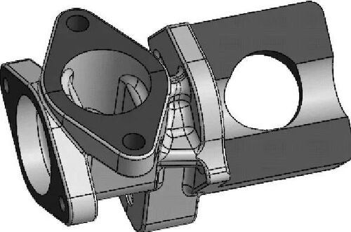
Figure 1 The three-dimensional structure of the casting
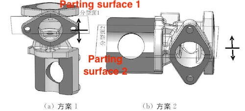
(a) Plan 1 (b) Plan 2
Figure 2 The parting surface scheme
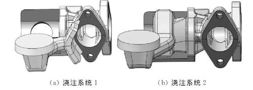
(a) Pouring system 1 (b) Pouring system 2
Figure 3 The three-dimensional structure of the pouring system
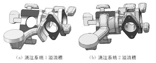
(a) Overflow trough of gating system 1 (b) Overflow trough of gating system 2
Figure 4 The three-dimensional structure of the overflow trough

Figure 5 The filling process of the pouring system 1

Figure 6 The filling process of the pouring system 2
(a) Pouring system 1 (b) Pouring system 2
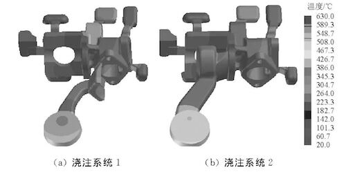
Figure 7 Temperature field of the casting after solidification
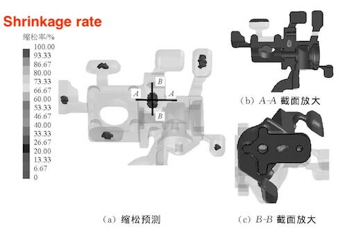
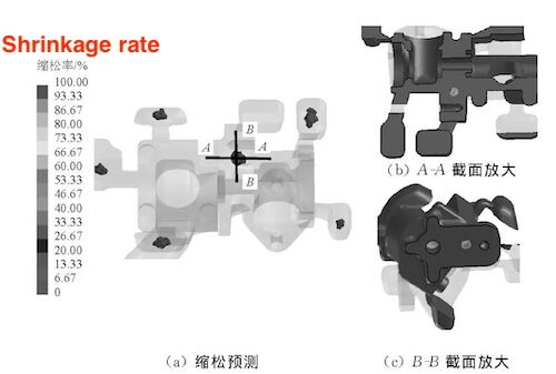
The predicted shrinkage for pouring system 1 are shown in Figure 8. As shown in Figure 8, shrinkage is observed in the thick-walled area of the casting. The shrinkage volume of the casting is 0.46 cm³ (excluding the overflow groove), and the shrinkage rate at the section ranges from 80% to 90%. Casting system 2 also exhibits shrinkage in the thick-walled area of the casting. The shrinkage volume is 0.16 cm³, with a shrinkage rate at the section of 80% to 85%, which is lower than the shrinkage exhibited by casting system 1. The primary reason is that, in casting system 1, the molten metal begins filling the thick-walled area earlier. During solidification, the temperature in the thick-walled area remains high, and the solidification rate is slow, increasing the likelihood of isolated liquid phases and shrinkage. Therefore, casting system 2 is more effective.
(b) Enlarged view of the A-A section
(a) Shrinkage prediction
(c) Enlarged view of the B-B section
Figure 8 Shrinkage distribution of casting system 1
(b) Enlarged view of the A-A section
(a) Shrinkage prediction
(c) Enlarged view of the B-B section
Figure 9 Simulation results of shrinkage distribution of castings produced by casting system 2
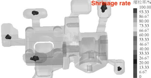
Figure 10 Shrinkage of castings after process optimization
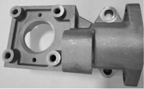
Figure 11 Castings
After analyzing the valve body structure, two die-casting processes were designed and numerically simulated. The results show that shrinkage occurs in the thick-walled area of the casting. Filling the thick-walled area with molten metal first results in more shrinkage. The shrinkage occurs because the solidification rate in the thick-walled area of the casting is slow, and some areas become isolated, unable to be compensated by the molten metal. The process was optimized by adding a cooling system to the thick-walled area. The results indicate that the optimized casting has no shrinkage and has been verified in production, meeting the technical requirements.
The casting is a valve body for an automobile oil cylinder component produced by a company. Its three-dimensional structural diagram is shown in Figure 1, where the dark gray area represents the processing surface. The processing allowance is 0.3mm. The dimensions are 115.5mm×74.5mm×71.9mm. The maximum wall thickness is 24.6mm; the minimum wall thickness is 2mm, and the main wall thickness is 7mm. The casting has a weight of 0.36kg, is made from ADC12, and its mechanical properties are shown in Table 1. The casting requires deburring, with a draft angle of 1.5° to 3° and a shrinkage rate of 0.5%. It is free from casting defects such as shrinkage cavities, cracks, and cold shuts, and the surface is shot peened.
Table 1 Mechanical properties of ADC12 alloy
| Property | Value |
| Yield Strength (MPa) | 140 |
| Tensile Strength (MPa) | 240 |
| Elongation (%) | ≥1 |
| Hardness (HRW) | 80 |

Figure 1 The three-dimensional structure of the casting

(a) Plan 1 (b) Plan 2
Figure 2 The parting surface scheme

(a) Pouring system 1 (b) Pouring system 2
Figure 3 The three-dimensional structure of the pouring system

(a) Overflow trough of gating system 1 (b) Overflow trough of gating system 2
Figure 4 The three-dimensional structure of the overflow trough

Figure 5 The filling process of the pouring system 1

Figure 6 The filling process of the pouring system 2

(a) Pouring system 1 (b) Pouring system 2
Figure 7 Temperature field of the casting after solidification
The predicted shrinkage for pouring system 1 are shown in Figure 8. As shown in Figure 8, shrinkage is observed in the thick-walled area of the casting. The shrinkage volume of the casting is 0.46 cm³ (excluding the overflow groove), and the shrinkage rate at the section ranges from 80% to 90%. Casting system 2 also exhibits shrinkage in the thick-walled area of the casting. The shrinkage volume is 0.16 cm³, with a shrinkage rate at the section of 80% to 85%, which is lower than the shrinkage exhibited by casting system 1. The primary reason is that, in casting system 1, the molten metal begins filling the thick-walled area earlier. During solidification, the temperature in the thick-walled area remains high, and the solidification rate is slow, increasing the likelihood of isolated liquid phases and shrinkage. Therefore, casting system 2 is more effective.

(b) Enlarged view of the A-A section
(a) Shrinkage prediction
(c) Enlarged view of the B-B section
Figure 8 Shrinkage distribution of casting system 1

(b) Enlarged view of the A-A section
(a) Shrinkage prediction
(c) Enlarged view of the B-B section
Figure 9 Simulation results of shrinkage distribution of castings produced by casting system 2

Figure 10 Shrinkage of castings after process optimization

Figure 11 Castings
After analyzing the valve body structure, two die-casting processes were designed and numerically simulated. The results show that shrinkage occurs in the thick-walled area of the casting. Filling the thick-walled area with molten metal first results in more shrinkage. The shrinkage occurs because the solidification rate in the thick-walled area of the casting is slow, and some areas become isolated, unable to be compensated by the molten metal. The process was optimized by adding a cooling system to the thick-walled area. The results indicate that the optimized casting has no shrinkage and has been verified in production, meeting the technical requirements.
Related News
- Impact of Heat Treatment on Mechanical Properties and Thermal Conductivity of ZL102 Alloy
- Impact of T6 Heat Treatment on ADC12 Aluminum Alloy Properties
- Enhancing the Mechanical Properties of ADC12 Aluminum Alloy via T6 Heat Treatment
- Die-Casting Process Design of Valve Bodies for Automobile Oil Cylinder Parts
- Temperature Field Simulation & Optimization of Automotive Housing Die Castings
- Research Status of High-Impact Aluminum Alloys Domestically and Internationally
- Die-cast Aluminum Castings for High-speed Rail Rocker Arm Shells
- Aluminum Alloys for Automobile Body Panels
- Analysis and Measures of Internal Shrinkage Cavities in Aluminum Die Castings
- Advantages of Aluminum Alloys in Lightweight Automobiles


