Temperature Field Simulation & Optimization of Automotive Housing Die Castings
An aluminum alloy housing is one of the key components for automobiles and is in high demand. A well-designed die-casting process can effectively reduce production costs and improve yield rates. To address issues in the actual die-casting production of the aluminum alloy housing, the die-casting process was simulated and analyzed for both flow field and temperature field, then optimized. The optimized process was used for trial production, aiming to produce high-quality die castings and provide a reference for the production of similar castings.
To address the problems in the production of aluminum alloy housing die-castings, casting mold flow analysis software was used to simulate the die-casting process, analyze the temperature field, and predict where shrinkage cavities and shrinkage are likely to occur. Two forced water cooling schemes were proposed to optimize the temperature field of the casting. The temperature fields of the two optimization schemes were compared and analyzed through numerical simulation, and the optimal die-casting scheme was determined. The castings produced by the optimized scheme were examined and found to have good internal quality, with shrinkage cavities and shrinkage completely eliminated.
To address the problems in the production of aluminum alloy housing die-castings, casting mold flow analysis software was used to simulate the die-casting process, analyze the temperature field, and predict where shrinkage cavities and shrinkage are likely to occur. Two forced water cooling schemes were proposed to optimize the temperature field of the casting. The temperature fields of the two optimization schemes were compared and analyzed through numerical simulation, and the optimal die-casting scheme was determined. The castings produced by the optimized scheme were examined and found to have good internal quality, with shrinkage cavities and shrinkage completely eliminated.
Optimization of Die-Casting Process for Aluminum Alloy Shell Parts
To address the problems in the die-casting production of aluminum alloy shell parts, the actual production casting process was simulated, analyzed, and optimized. By analyzing the temperature field distribution of the casting and predicting where shrinkage cavities and shrinkage are likely to occur, forced water cooling was adopted to enhance local cooling, and two optimization schemes were proposed based on the casting and mold structure. The two optimization schemes were compared and analyzed through numerical simulation to determine the optimal cooling scheme. Analysis of the castings produced by the optimal cooling scheme showed that internal shrinkage cavities and shrinkage were completely eliminated. The trial production demonstrated that the scheme effectively optimizes the solidification temperature field. The study demonstrates that the forced water cooling process significantly optimizes the temperature field in the thick and large sections on the periphery of the casting. Figure 1 shows a schematic diagram of the aluminum alloy shell casting and its pouring system. The casting is made from A356 alloy, weighs approximately 0.632 kg, contains multiple internal cavities, and features complex mold core-pulling sections. The minimum wall thickness is 2.6 mm, the maximum is 10.6 mm, and the average is approximately 4.0 mm, with an uneven distribution. Analysis of the casting structure revealed that the maximum wall thickness is located at the periphery of section A of the casting.
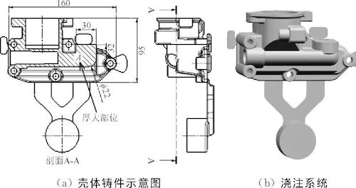
(a) The shell casting (b) Pouring system
Figure 1 Aluminum alloy shell casting and pouring system


Figure 2 Filling flow field of the initial scheme

Figure 3 Temperature field simulation of the casting of the initial scheme

Figure 4 Sectional temperature field of the casting at A of the initial scheme
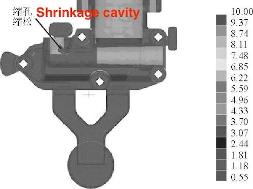
Figure 5 Shrinkage and its distribution of the initial scheme
Table 1 Simulation parameters and boundary conditions

(a) The shell casting (b) Pouring system
Figure 1 Aluminum alloy shell casting and pouring system


Figure 2 Filling flow field of the initial scheme

Figure 3 Temperature field simulation of the casting of the initial scheme

Figure 4 Sectional temperature field of the casting at A of the initial scheme

Figure 5 Shrinkage and its distribution of the initial scheme
Table 1 Simulation parameters and boundary conditions
| Mold-environment heat transfer coefficient (W•m⁻²•K⁻¹) | Mold-casting heat transfer coefficient (W•m⁻²•K⁻¹) | Mold-mold heat transfer coefficient (W•m⁻²•K⁻¹) | |
| 25 | 1000 | 1500 | |
| Mold temperature (°C) | Environment temperature (°C) | Pouring temperature (°C) | Pouring speed (m/s) |
| 220 | 25 | 650 | 3.0 |
To optimize the solidification temperature field of the casting and avoid shrinkage at point A, it is necessary to adopt a method that accelerates local cooling. Since the wall thickness at point A is much greater than the surrounding areas, the optimization scheme proposes using forced water cooling to accelerate the cooling process. After analyzing the casting and mold structure, two optimization schemes were designed near point A, as shown in Figure 6. The diameter of the cooling water pipe is 20 mm. During the optimization simulation, the circulating cooling water temperature was set to 30°C, and the surface heat transfer coefficient between the water and mold was set to 5,000 W/(㎡·K).
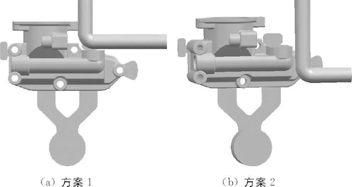
(a) Plan 1 (b) Plan 2
Figure 6 Design scheme for optimized temperature field of cooling water channel

Figure 7 Section temperature field at A of plan 1

Figure 8 Section temperature field at A of plan 2
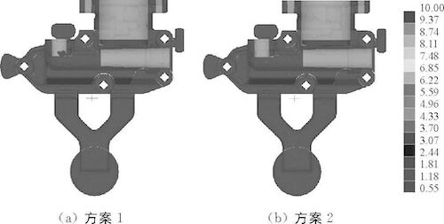

Figure 7 Section temperature field at A of plan 1

Figure 8 Section temperature field at A of plan 2

(a) Plan 1 (b) Plan 2
Figure 9 Prediction results of shrinkage and porosity of castings in plan 1 and plan 2
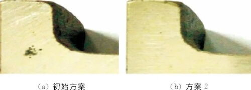
(a) Initial plan (b) Plan 2
Figure 10 Analysis of A of pilot production castings in the initial scheme and optimized scheme 2

(a) Initial plan (b) Plan 2
Figure 10 Analysis of A of pilot production castings in the initial scheme and optimized scheme 2
Related News
- Impact of Heat Treatment on Mechanical Properties and Thermal Conductivity of ZL102 Alloy
- Impact of T6 Heat Treatment on ADC12 Aluminum Alloy Properties
- Enhancing the Mechanical Properties of ADC12 Aluminum Alloy via T6 Heat Treatment
- Die-Casting Process Design of Valve Bodies for Automobile Oil Cylinder Parts
- Temperature Field Simulation & Optimization of Automotive Housing Die Castings
- Research Status of High-Impact Aluminum Alloys Domestically and Internationally
- Die-cast Aluminum Castings for High-speed Rail Rocker Arm Shells
- Aluminum Alloys for Automobile Body Panels
- Analysis and Measures of Internal Shrinkage Cavities in Aluminum Die Castings
- Advantages of Aluminum Alloys in Lightweight Automobiles


